- 您现在的位置:买卖IC网 > Sheet目录3872 > PIC16C57C-04/SP (Microchip Technology)IC MCU OTP 2KX12 28DIP
PIC18F2450/4450
DS39760A-page 96
Advance Information
2006 Microchip Technology Inc.
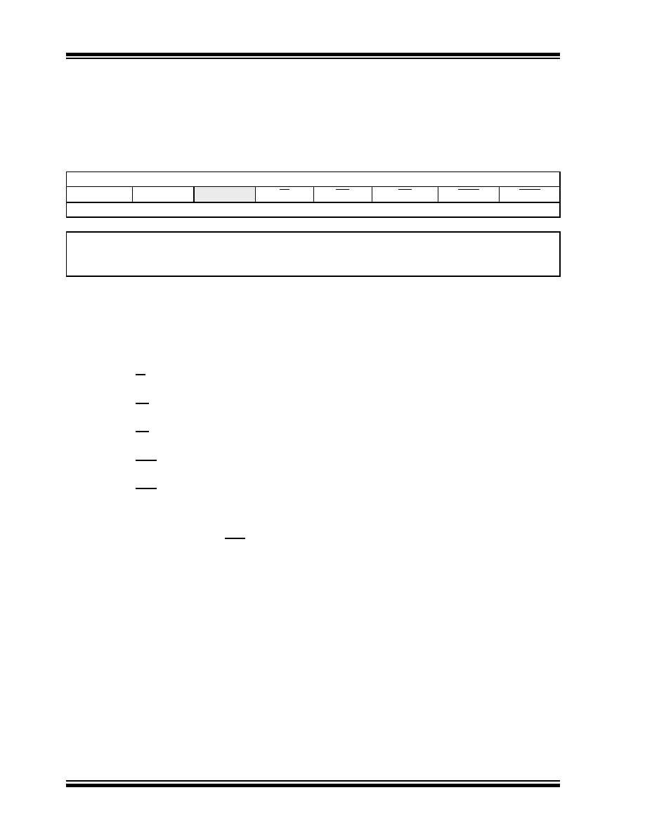
8.6
RCON Register
The RCON register contains flag bits which are used to
determine the cause of the last Reset or wake-up from
Idle or Sleep modes. RCON also contains the IPEN bit
which enables interrupt priorities.
REGISTER 8-10:
RCON: RESET CONTROL REGISTER
R/W-0
R/W-1(1)
U-0
R/W-1
R-1
R/W-0(2)
R/W-0
IPEN
SBOREN
—RI
TO
PD
POR
BOR
bit 7
bit 0
Legend:
R = Readable bit
W = Writable bit
U = Unimplemented bit, read as ‘0’
-n = Value at POR
‘1’ = Bit is set
‘0’ = Bit is cleared
x = Bit is unknown
bit 7
IPEN: Interrupt Priority Enable bit
1
= Enable priority levels on interrupts
0
= Disable priority levels on interrupts (PIC16CXXX Compatibility mode)
bit 6
SBOREN: BOR Software Enable bit(1)
For details of bit operation, see Register 4-1.
bit 5
Unimplemented: Read as ‘0’
bit 4
RI: RESET Instruction Flag bit
For details of bit operation, see Register 4-1.
bit 3
TO: Watchdog Time-out Flag bit
For details of bit operation, see Register 4-1.
bit 2
PD: Power-Down Detection Flag bit
For details of bit operation, see Register 4-1.
bit 1
POR: Power-on Reset Status bit(2)
For details of bit operation, see Register 4-1.
bit 0
BOR: Brown-out Reset Status bit
For details of bit operation, see Register 4-1.
Note 1:
If SBOREN is enabled, its Reset state is ‘1’; otherwise, it is ‘0’. See Register 4-1 for additional information.
2:
The actual Reset value of POR is determined by the type of device Reset. See Register 4-1 for additional
information.
发布紧急采购,3分钟左右您将得到回复。
相关PDF资料
PIC16LF628A-I/SO
IC MCU FLASH 2KX14 EEPROM 18SOIC
PIC16C55A-20/SO
IC MCU OTP 512X12 28SOIC
PIC24F16KA101-I/MQ
IC PIC MCU FLASH 16KB 20-QFN
PIC16F627-04/SO
IC MCU FLASH 1KX14 COMP 18SOIC
PIC16C58B-20I/P
IC MCU OTP 2KX12 18DIP
PIC24FJ16GA002-I/SS
IC PIC MCU FLASH 16K 28-SSOP
PIC16C55A-04I/SO
IC MCU OTP 512X12 28SOIC
PIC16CR77-I/ML
IC PIC MCU 8KX14 44QFN
相关代理商/技术参数
PIC16C57C-04/SP
制造商:Microchip Technology Inc 功能描述:IC 8BIT CMOS MCU 16C57 SDIL28
PIC16C57C-04/SP
制造商:Microchip Technology Inc 功能描述:Microcontroller IC Number of I/Os:20
PIC16C57C-04/SS
功能描述:8位微控制器 -MCU 3KB 72 RAM 20 I/O RoHS:否 制造商:Silicon Labs 核心:8051 处理器系列:C8051F39x 数据总线宽度:8 bit 最大时钟频率:50 MHz 程序存储器大小:16 KB 数据 RAM 大小:1 KB 片上 ADC:Yes 工作电源电压:1.8 V to 3.6 V 工作温度范围:- 40 C to + 105 C 封装 / 箱体:QFN-20 安装风格:SMD/SMT
PIC16C57C-04E/P
功能描述:8位微控制器 -MCU 3KB 72 RAM 20 I/O RoHS:否 制造商:Silicon Labs 核心:8051 处理器系列:C8051F39x 数据总线宽度:8 bit 最大时钟频率:50 MHz 程序存储器大小:16 KB 数据 RAM 大小:1 KB 片上 ADC:Yes 工作电源电压:1.8 V to 3.6 V 工作温度范围:- 40 C to + 105 C 封装 / 箱体:QFN-20 安装风格:SMD/SMT
PIC16C57C-04E/SO
功能描述:8位微控制器 -MCU 3KB 72 RAM 20 I/O RoHS:否 制造商:Silicon Labs 核心:8051 处理器系列:C8051F39x 数据总线宽度:8 bit 最大时钟频率:50 MHz 程序存储器大小:16 KB 数据 RAM 大小:1 KB 片上 ADC:Yes 工作电源电压:1.8 V to 3.6 V 工作温度范围:- 40 C to + 105 C 封装 / 箱体:QFN-20 安装风格:SMD/SMT
PIC16C57C-04E/SP
功能描述:8位微控制器 -MCU 3KB 72 RAM 20 I/O RoHS:否 制造商:Silicon Labs 核心:8051 处理器系列:C8051F39x 数据总线宽度:8 bit 最大时钟频率:50 MHz 程序存储器大小:16 KB 数据 RAM 大小:1 KB 片上 ADC:Yes 工作电源电压:1.8 V to 3.6 V 工作温度范围:- 40 C to + 105 C 封装 / 箱体:QFN-20 安装风格:SMD/SMT
PIC16C57C-04E/SS
功能描述:8位微控制器 -MCU 3KB 72 RAM 20 I/O RoHS:否 制造商:Silicon Labs 核心:8051 处理器系列:C8051F39x 数据总线宽度:8 bit 最大时钟频率:50 MHz 程序存储器大小:16 KB 数据 RAM 大小:1 KB 片上 ADC:Yes 工作电源电压:1.8 V to 3.6 V 工作温度范围:- 40 C to + 105 C 封装 / 箱体:QFN-20 安装风格:SMD/SMT
PIC16C57C-04I/P
功能描述:8位微控制器 -MCU 3KB 72 RAM 20 I/O RoHS:否 制造商:Silicon Labs 核心:8051 处理器系列:C8051F39x 数据总线宽度:8 bit 最大时钟频率:50 MHz 程序存储器大小:16 KB 数据 RAM 大小:1 KB 片上 ADC:Yes 工作电源电压:1.8 V to 3.6 V 工作温度范围:- 40 C to + 105 C 封装 / 箱体:QFN-20 安装风格:SMD/SMT